Zener's Theory of Electrical Breakdown in Insulators
Lecture notes by Dmitri Y. Petrovykh, based on Proc. Roy. Soc. A 524 (1934).
Physics Department, University of Wisconsin, Madison, WI, USA (1999)
- Introduction
- Zener's Model
- Bloch Functions in Electric Field
- Tunneling attempt frequency
- Tunneling probability
- Results and discussion
Introduction
A simplest model of an insulator is a solid in which there exists a number of bands completely filled with electrons (valence bands, VB) and a number of bands of higher energy (conduction bands, CB) which are empty (Fig. 1a). The two bands are separated by the forbidden energy gaps, where electrons are not allowed. This model is true for perfect infinite crystals at zero temperature. At finite temperature and in the presence of defects there will be some electrons in the CB, but their small number precludes any conductivity at ordinary electric field strengths.
 and empty conduction bands (CB) separated by forbidden energy gaps.")
Fig.1 Band structure of a simple insulator with filled valence bands (VB) and empty conduction bands (CB) separated by forbidden energy gaps. Electrons of a given energy (horizontal line) (a) can not move between the bands without electric field, and (b) can be in the different bands with electric field F present.
It is a well-known fact, however, that when the field reaches a certain critical strength a dielectric breakdown occurs. A sudden increase in the current and thus the number of electrons in the CB is observed. Any model of the breakdown should therefore account for the following two features:
- a sudden rather than monotonic increase in the current once the critical field is attained,
- a prediction of the critical field strength that agrees with experimental values.
Zener's Model
Zener has proposed a conceptually simple model that lends itself to reasonably straightforward evaluation. The idea is presented in Fig. 1b. While an electron is effectively confined to the VB with no electric field present, once a sufficiently strong uniform field is applied the bands become effectively "tilted". That tilt allows an electron originating in the VB to pass into the CB, without the necessity of having the extra energy to cross the gap between the two bands. Instead, the gap should be treated as an effective barrier and the problem reduces to considering the tunneling process through such a barrier.
When a tunneling process is considered in quantum mechanics, there are usually three steps involved in solving the problem:
- Choose/find/construct correct wavefunctions to describe the particle throughout the motion
- Find the attempt frequency (i.e. how often does the particle try to cross the barrier)
- Find the tunneling probability (i.e. what is the probability to actually cross in each attempt)
Bloch Functions for Electrons in a Weak Constant Electric Field
Bloch's Theorem tells us that solutions to the 1D wave equation with a periodic potential are:
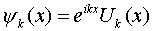 (1)
(1)
When a weak electric field is present the wave function can be expanded in terms of these solutions as:
where 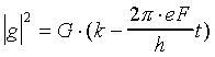 ,
G is an arbitrary function, a—the lattice
constant, e—the electron charge.
,
G is an arbitrary function, a—the lattice
constant, e—the electron charge.
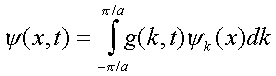
We can see that  moves in k-space
with the velocity
moves in k-space
with the velocity  .
.
is a periodic function of time. Since
the range of k is 2π/a, the frequency ν is:
 (2)
(2)
The velocity of the electron can be written as
where Vk is the velocity of an electron in state
k. Given the periodicity of discussed
above, we conclude that the velocity of the electron is also a
periodic function of time with the frequency ν.
The Attempt Frequency
Qualitatively, the electron wavefunction constructed above, describes an electron by a wave packet confined to the VB, with electron moving in the direction of the field until it is reflected by the barrier. Once reflected, it moves in the opposite direction, until it is stopped by the field and so on.
One immediately recognizes the typical setup for a tunneling problem in quantum mechanics. To find the actual tunneling rate (i.e., the probability of tunneling per unit time γ) we need the attempt frequency ν and the tunneling probability p. Luckily, we have just calculated the attempt frequency ν (Eq 2). So now we just need the tunneling probability p, to find the tunneling rate γ as:
γ = pν (3)
The Tunneling Probability
It turns out that the calculation of the tunneling probability is the most strenuous part of this exercise. Furthermore, it is easier evaluated for an electron represented by ψ(x,t) periodic in time, not by a wave packet used above. For the wavefunction periodic in time, the spatial part of the wave equation becomes:
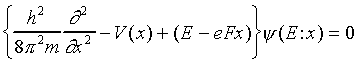
The only difference between the above expression and the "conventional" problem of the tunneling through a barrier V(x) is the extra term eFx in the particle's energy. However, this term does not change in the distance of a single lattice constant a, whereas the periodic potential does change significantly over a.
Recall that the general solution for a tunneling problem has the
form:  , where
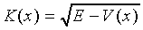
In our case, neglecting the variability of the eFx term over a, we can then write the approximate solution for the periodic potential as:
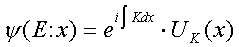
where K is the same function of (E − eFx) as it is of E when F = 0, and UK is identical to Uk of (Eq 1) with k = K. This K obviously becomes complex in the gap (barrier) region, which corresponds to exponential increasing or decreasing wavefunction in the barrier region. We take the decreasing case to have a physically meaningful result. This exponentially damped function then has to be matched to essentially unchanged wavefunctions from the VB and the CB on the respective sides of the gap (Fig. 2).

Fig. 2 Schematic representation of the tunneling in the presence of the electric field. Electron wavefunction is approximated by the regular wavefunctions in VB and CB regions, and is exponentially damped in the forbidden (gap) region.
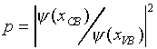
The transition probability is then simply
 .
.
The attenuation is due to the imaginary part of K, so if we express K as K = ξ(x) + iη(x), the attenuation becomes:
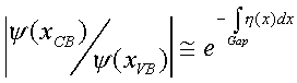
The transition probability then is:
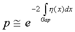
If we now recall the result for the attempt frequency (Eq 2), the tunneling rate given by (Eq 3) becomes:
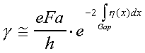
Results and Discussion
We now have the general form of the solution to our problem and all the three steps of our original "program" have been completed. The only missing part is the expression for η(x) (or for K) that we could integrate to estimate γ. Such expression can be obtained by solving the wave equation as a Hill's equation, but the solution is rather cumbersome to be presented in full. Here we will just use the result obtained by Zener in the original paper.
The tunneling rate obtained by Zener is:
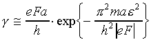 (4)
(4)
where ε is the energy gap between the VB and the CB.
If we assume reasonable values ε = 2 eV and a = 3*10-8 cm, then for electric field F* in V/cm:

In good agreement with experimental observations, critical electric field strength is on the order of 106 V/cm. Sudden increase of γ (and thus the current) is reflected in this model as well, e.g., for a change in F* from 1.0*107 to 1.1*107 V/cm, F* is being increased by a factor of 100. Therefore this simple model can account alone for the experimentally observed electrical breakdown of dielectrics.
A few notes are in order, concerning the general applicability of this model:
- All the calculations were performed for a 1-dimensional lattice, however, it is to be expected that the results obtained are true in general for a 3-dimensional lattice.
- In the derivation of (Eq 4) it was assumed that the first Fourier coefficient of the potential energy of an electron in the lattice is small (<< 4 eV for a = 3*10-8 cm). For most crystals this assumption is incorrect, but the general dependence of γ on the energy gap ε will still be valid.
- For metals, the obtainable field strengths are much lower, so the transitions between different bands become negligible. For a = 3*10-8 cm and F* = 1 an electron will pass an energy gap as small as 2*10-3 eV only after a period of years.
 surface")